Dr. Lina Chong from the School of Materials Science and Engineering at Shanghai Jiao Tong University made a breakthrough in the research area of precious metal free catalyst for oxygen evolution reaction at the anode of proton exchange membrane eletrolyzer, which was published in the prestigious magazine “Science” and entitled "La- and Mn-doped cobalt spinel oxygen evolution catalyst for proton exchange membrane electrolysis" (https://www.science.org/doi/10.1126/science.ade1499). The work was also awarded “R&D 100 Award” in 2022 that entitled “PGM-free OER Catalyst as Replacement of Iridium for PEM Water Electrolyzer”. The work reported a lanthanum and manganese co-doped cobalt spinel-based OER catalyst derived from zeolitic methyl-imidazolate framework (Co-ZIF) and processed by electrospinning. The catalyst demonstrated an excellent oxygen evolution reaction (OER) activity, showing an overpotential as low as 353 mV at 10 mA cm-2 and sustained catalyzing water oxidation over 360 hours in acidic media. Furthermore, a PEMWE containing this catalyst at the anode demonstrated a current density of 2000 mA cm-2 at 2.47 V (Nafion 115) or 4000 mA cm-2 at 3.00 Vs (Nafion 212) and low degradation in an accelerated stress test.
Dr. Lina Chong published her work in prestigious magazine Science.
Low-temperature water electrolysis can rapidly produce environmentally sustainable, or green, hydrogen and is a prospective means of storing energy from renewable but intermittent power sources, such as wind and solar, in future clean energy infrastructure. Commercial systems use either liquid alkaline electrolyte or proton exchange membrane electrolyte. Compared with the alkaline counterpart, a proton exchange membrane water electrolyzer (PEMWE) offers the advantages of higher current density, higher H2 purity, lower resistance losses, and more compact design, rendering it a preferred technology where high efficiency and small footprint are essential. Working under the acidic and oxidative environment, however, adds substantial challenges to the catalyst activity and stability profile. This is particularly the case for the anode catalyst because of the high overpotential for oxygen evolution reaction (OER). At present, OER catalysts for PEMWE are primarily restricted to the platinum group metal (PGM) materials, such as IrOx. Their high cost and limited reserve, however, pose substantial barriers to the widespread implementation of PEMWE. Low-cost transition metals and their oxides are known to be active toward OER in alkaline electrolyte (4–6), but their demonstration in acidic electrolyte is very limited.
Cobalt molecular and oxide compounds have emerged as promising OER catalysts for water splitting in recent years. However, most of them were carried out either in half-cells or aqueous electrolyzers, where the demands for OER catalyst stability and conductivity are different from those in a PEMWE. Effective OER for PEMWE requires optimal interfacial properties, microporosity, and surface catalytic activity, all of which need to be validated in the operating electrolyzer.
Our design concept of an efficient cobalt spinel–based OER catalyst for PEMWE anodes is based on the following rationale: To enhance OER activity in acid, an oversized and more stable second element can be selectively introduced to the cobalt oxide surface to generate strain, oxygen vacancy (Vo), and acid tolerance; to improve the oxide electronic conductivity, a third element with similar charge and dimension to cobalt may be incorporated inside the lattice to bridge the Fermi bandgap through d orbital partial occupation of the third element induced by its d-electron delocalization. Advancing further from the rotating disk electrode (RDE) or half-cell study to a membrane electrode assembly (MEA) demonstration, the catalyst should have a high porosity and surface area easily accessible to the reactant (H2O). Meanwhile, the electrode layer should be effective in transporting H2O and releasing O2 without blocking the water-catalyst interface. Furthermore, the oxide catalyst should be self-conductive without the need for another conductive support, such as carbon, that is unstable under high OER operating potential and current density. Finally, the metal oxide should be stable against oxidative and acidic (pH 2 to 4) corrosion in the PEMWE environment.
Inspired by this concept, LaMn@Co-ZIF was synthesized, and then was suspended in a polyacrylonitrile (PAN) polymer slurry (LaMn@Co-ZIF/PAN), followed by being electrospun into a fibrous mat. The nanofiber embedded with individual LaMn@Co-ZIF was activated in flowing air at 360℃ for 6 hours to remove the organic components, forming La and Mn-co doped porous cobalt spinel fibers (denoted LMCF) (Fig. 1A). The SEM image of LMCF shows an interconnected nanofibrous network morphology with ample macropores in between the entwined nanofibers (Fig. 1B). High-angle annular dark-field scanning transmission electron microscopy (HAADF-STEM) revealed that individual LMCF particles retained the original Co-ZIF’s rhombic dodecahedral shape, aligned and fused together in strings after oxidation (Fig. 1C). The ZIF-shaped LMCF particle is highly porous with a hollow structure composed of nanopores, as shown by transmission electron microscopy (TEM) (Fig. 1D). Each particle is composed of aggregates of Co3O4 nanocrystallites, with an average size of ~3.5 nm (Fig. 1E). STEM images showed that the individual crystal surface was dominated by (111) facets, and electron energy loss spectroscopy (EELS) elemental mapping revealed La localization on the surface, with Mn distributed mainly in the bulk (Fig. 1, F to H). HRTEM imaging revealed that the LMCF lattice surface was terminated by oxygen atoms in a relaxed state, with positions shifted from those inside the crystallite due to Vo (Fig. 1I), an important attribute in lowering the OER activation energy and stabilizing the intermediate during the reaction.
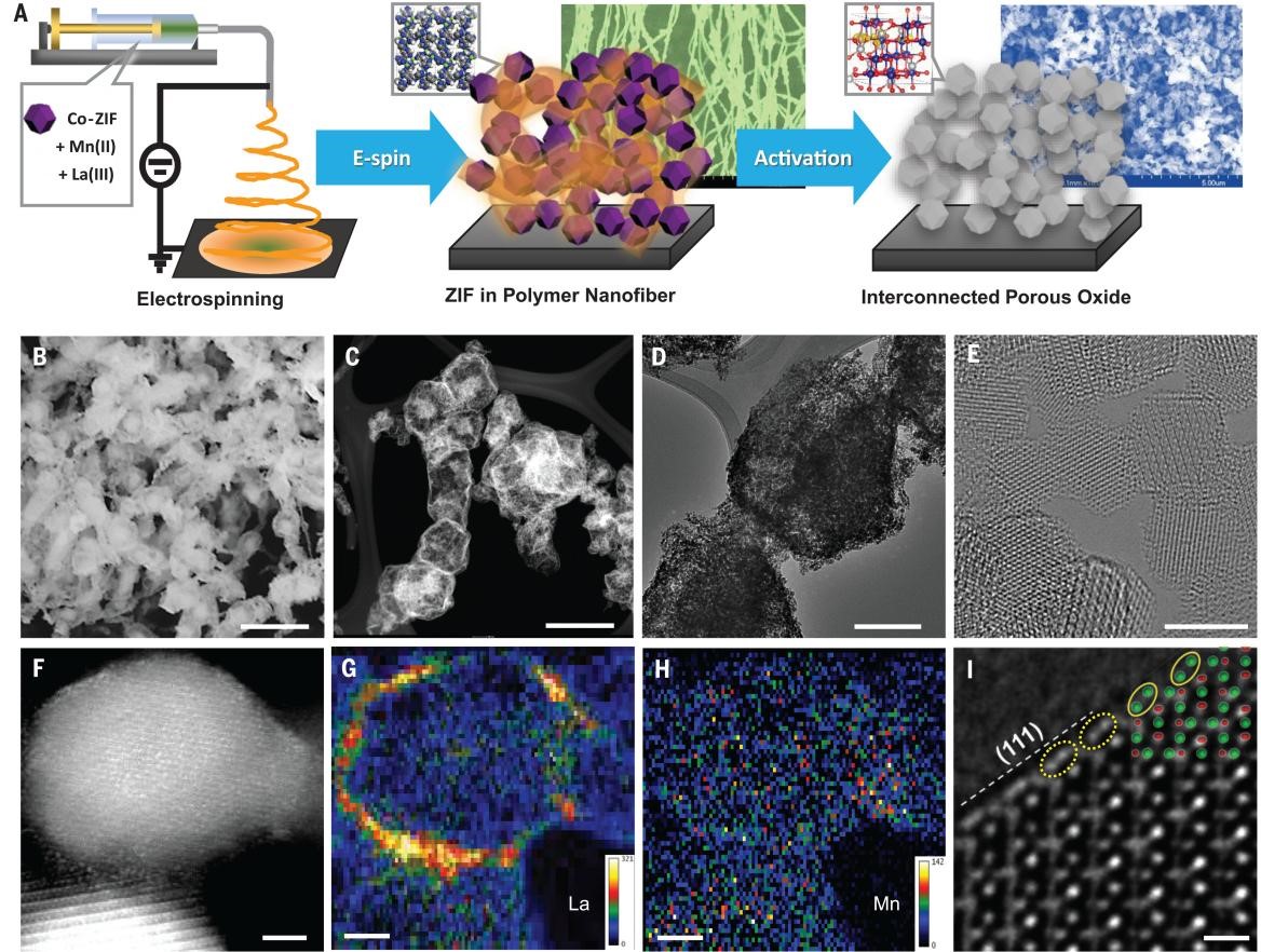
Fig. 1. Synthesis, morphology, and structure of LMCF.(A) Schematics of LMCF synthesis including formation of Co-ZIF embedded PAN polymer fiber by electrospinning and thermal oxidative activation to produce interconnected porous cobalt oxide particles after removing all the organics. The background SEM images show a cross-linked, ZIF-containing fiber nanonetwork produced by electrospinning and the interconnected porous oxide after the activation. (B) SEM image (scale bar, 1 μm). (C) HAADF-STEM image (scale bar, 500 nm). (D) TEM image (scale bar, 200 nm). (E) HRTEM image (scale bar, 5 nm). (F to H) STEM image and the corresponding La and Mn distributions (scale bar, 2 nm). The color bars show the element counts. The maximal counts are 321 for La and 142 for Mn. (I) HRTEM image (scale bar, 0.5 nm). The green dots represent atomic columns of tetrahedral (T) and octahedral (O) oxygens, and the red dots represent the cobalt atomic columns simulated based on bulk phase inside lattice. The dotted yellow ellipses (on surface) show a different orientation compared with the solid yellow ellipses from the simulation (in bulk), suggesting a shift of oxygen position as a result of lattice relaxation.
The x-ray absorption near-edge structure (XANES) spectrum at the Co K-edge (LMCF) shows a very similar spectral pattern to that of Co3O4 with a slightly red-shifted absorption energy and a decreased white line (WL) intensity (Fig. 2A), indicating a lower average oxidation state and a smaller O coordination number (CN) to cobalt in LMCF, which agrees well with the Raman and XPS results. An enhanced 1s → 3d transition peak intensity can be observed, which reveals that the cobalt in LMCF is in a less centrosymmetric coordination environment than that in Co3O4, suggesting a distorted Co oxide lattice by Vo. Compared with Co3O4, the LMCF extended X-ray absorption fine structure (EXAFS) shows lower peak intensities and CNs corresponding to Co-O and Co-Co shells (Fig. 2D), which further supports a less developed lattice with a high concentration of Vo from smaller particle size and higher Co2+ (tetrahedral O-coordinated) fraction in LMCF. XANES at the Mn K-edge indicates that the average manganese oxidation state is between +3 and +4 (Fig. 2B). Both K-space and R-space spectra extracted from EXAFS exhibit significant differences from that in Mn oxide references (Mn3O4, Mn2O3, and MnO2) (Fig.2 B and C). The results confirm that the Mn substitutes for the Co3+ at the edge-sharing octahedral site and is embedded inside the cobalt oxide matrix in LMCF, in agreement with the HAADFSTEM result. The XANES spectrum of La in LMCF shows significantly higher WL intensity than that of the La2O3 reference (Fig. 2C). Given that the WL intensity for oxides is generally proportional to the number of coordinated oxygens, R-space fitting determined the CN of La to oxygen in LMCF to be 8.3, which is in between that of lanthanum oxide (CN = 6) and hydroxide (CN = 9).
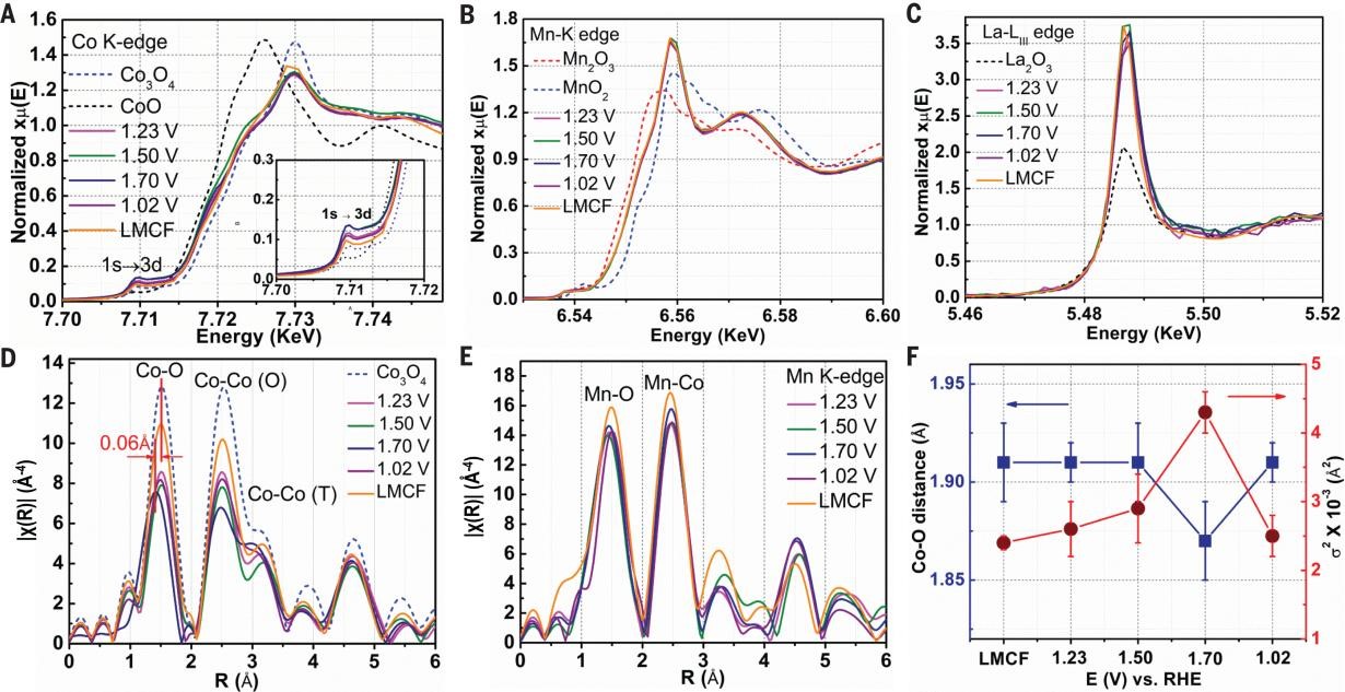
Fig. 2. XAS study of LMCF. (A to C) Fluorescence XANES spectra collected at Co K-edge (A) (inset: enlarged pre-edge 1s → 3d transition), Mn K-edge (B), and La LIII-edge (C) under ex situ (LMCF) and operando conditions at different potentials. Co3O4, CoO, Mn2O3, MnO2, and La2O3 are used as the references. (D and E) R-space EXAFS spectra at Co K-edge (D) and Mn K-edge (E) of the same samples. (F) Co-O bond distances (blue line) and DWF (red line) surround Co derived from EXAFS data taken at different cell potentials. Error bars represent the uncertainty of Fourier transformation of the experimental EXAFS data.
The OER catalytic activity of LMCF was first evaluated using the RDE method in 0.1 M HClO4 electrolyte (pH = 1). Figure 3A shows a progressive improvement of OER activity measured by cyclic voltammogram (CV) through the addition of Mn and La in CF. The performance of LMCF also significantly exceeds that of commercial Co3O4 and approaches that of Ir black. Figure 3B presents the mass activity (MA) Tafel plot for LMCF together with the benchmark samples. LMCF again exhibits a high intrinsic catalytic activity. LMCF was subjected to an accelerated aging test through voltage cycling between 1.4 V and 2.0 V versus reversible hydrogen electrode (RHE) by RDE in 0.1 M HClO4 electrolyte. A mere ~20-mV potential loss at 10 mA cm-2 was observed after 14,000 CV cycles (Fig. 3C). Furthermore, its durability in acidic media was evaluated by holding the electrode current density at 10 mA cm-2 for an extended operation period of over 353 hours (Fig. 3D). The stability number (S number) for LMCF was also calculated based on the amount of Co dissolved in the electrolyte at different testing times. These values are compared with some of the Ir-based benchmarks in the literature, and the LMCF stability was found to be comparable to some less-stable Ir materials (Fig. 3E).
Furthermore, the LMCF was assembled into the anode of a PEMWE single cell and tested using deionized (DI) water as the feed. Figure 3F shows composite current-voltage polarization curves derived from three measurements in the PEMWE. The electrolyzer reached a current density of 2000 mA cm-2 at a voltage of 2.47 V (2.20 V after cell iR correction), which could be further reduced to 2.30 V by switching the membrane from Nafion 115 to Nafion 212, and reached a current density of 4000 ± 200 mA cm-2 at 3.0 V. The MEA with LCMF was also subjected to accelerated stress tests (ASTs) using voltage cycling, chronopotentiometry methods, and the membrane electrode containing LMCF demonstrated excellent cycling stability (Fig. 3G, H, I).
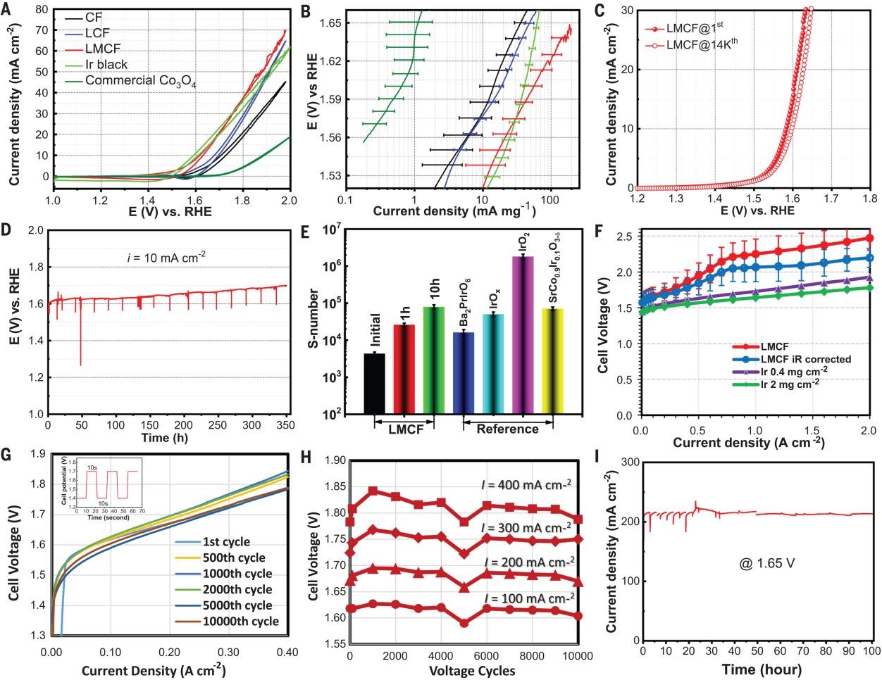
Fig. 3. Electrocatalytic performance of LMCF. (A) CVs of LMCF, LCF, CF, Ir black, and commercial Co3O4 in O2-saturated 0.1 M HClO4 (PGM-free catalyst loadings = ~260 ± 30 μg cm−2, Ir black loading = ~230 ± 30 μg cm−2). (B) Tafel plots of LMCF, LCF, CF, Ir black, and commercial Co3O4, with error bars of one standard deviation over four experimental replicates. (C) LSVs of LMCF measured by RDE before and after 14,000 voltage cycles in O2-saturated 0.1 M HClO4 (with 95% iR correction). (D) Chronopotentiometric response at 10 mA cm−2 with LMCF catalyst loading of 0.9 mg cm−2 over 353-hour test. (E) S number calculated for LMCF after different hours onstream compared with selected benchmark Ir-based catalysts. (F) Current-voltage polarizations (iR corrected and uncorrected) of the PEMWE cell with LMCF anodic catalyst compared with that of Ir black catalysts with different loadings at 80°C. The polarization plot for LMCF represents an average of three MEA measurements with one standard deviation. (G) Current-voltage polarizations of the PEMWE after selected cycle numbers during a multiple-voltage cycling AST. The inset shows the stepwise voltage swing between 1.4 V and 1.7 V with 10-s dwell time at each potential. (H) PEMWE cell voltage measured at different current densities after selected voltage cycles during the AST. (I) Potentiostatic measurement of PEMWE at the cell potential of 1.65 V for LMCF anodic catalyst over 100 hours.
To understand the nature of the active site and the impact of the second and third metal doping, in situ XAS of LMCF was performed in an O2-saturated electrolysis cell (0.1 M HClO4)
at the Co, Mn K-edge, and La-LIII edge. (1) When the OER reaction proceeds much more rapidly, XAS analysis shows shortening of the Co-O bond length (Fig. 2F), indicating a high degree of covalency contraction. (2) A reversible cobalt-oxygen coordination and lattice oxygen participation during the OER process were observed. (3) Mn and La do not participate in the electrocatalysis directly. Rather, their presence modifies the structure and activity of the cobalt site. (4) The calculated Pourbaix diagram demonstrates that the stability of the LMCF catalyst is defined by the combination of cell potential and pH. In fact, the industry PEMWE anode operates in a window within the green diagonal stripes that applied to LMCF, demonstrating the stability of LMCF in operating PEMWE (Figure 4A and 4B). (5) Doping with La improves the stability of Co3O4 structure under acid, and substituting Co with Mn improves the electronic conductivity of the catalyst (Figure 4C and 4D). These improvements delivered by this work offer paths to the next-generation, PGM-free OER catalysts as viable replacements for precious metals, such as iridium.
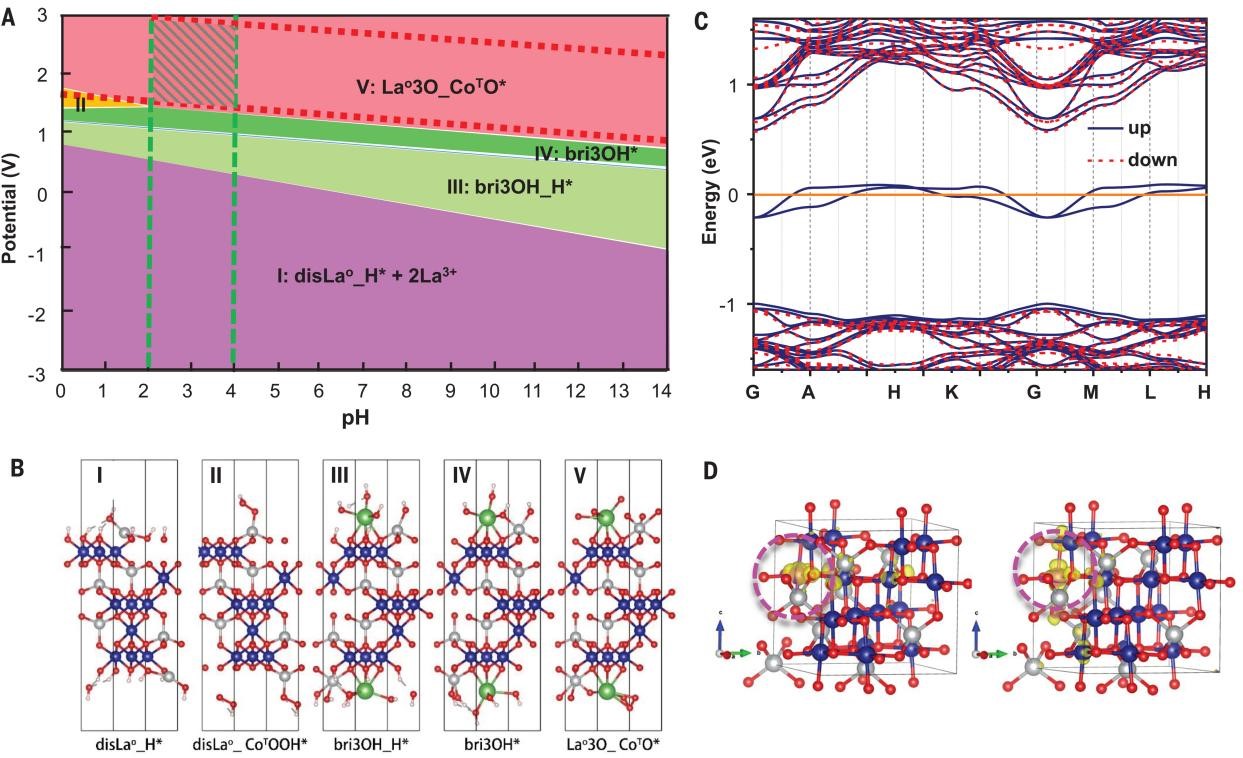
Fig. 4. Computational Pourbaix diagram and Fermi band structure of LMCF. (A) Surface Pourbaix diagram for the La-doped Co3O4 (111) facet obtained from the DFT + U calculations. (B) Possible intermediate state configurations. Blue, gray, red, and white balls denote the octahedral Co3+, tetrahedral Co2+, oxygen, and hydrogen ions. An asterisk denotes the pure surface; H* and _H* denote the configurations in which the surface oxygen atoms are covered by H; CoO denotes the octahedral coordinated cobalt, and CoT denotes the tetrahedral coordinated cobalt; the nO/nOH/nOOH refer to the numbers of O/OH/OOH groups covering over each Co atom; configurations denoted “disCo/La” are generated after the Co/La dissolution; and the prefix “bri-” means that the covered groups act as a bridge connecting LaO and CoT. The potential is relative to the standard hydrogen electrode (SHE). (C) Calculated Fermi band structure of LMCF by replacing Co3+ with Mn3+ in the Co3O4 lattice. (D) Charge density distribution at the Fermi level upon Mn substitution in LMCF. Yellow refers to the charge density contour. Blue, gray, and red balls indicate octahedral Co3+, tetrahedral Co2+, and oxygen, respectively. Mn ions are behind yellow contour and circled by violet dotted line.